LS Coil Instructions
LS Coil Instructions
Note - we haven’t completed the instructions for the R8 coil kit yet. It’s basically the same, so just follow these instructions. Scroll to the very bottom for R8 coil notes.
The complete kit comes with four main sets of components_ a coil bracket that fits on the intake side of the valve cover, 4x LS2 truck coils, 4x spark plug wires, and wiring components.
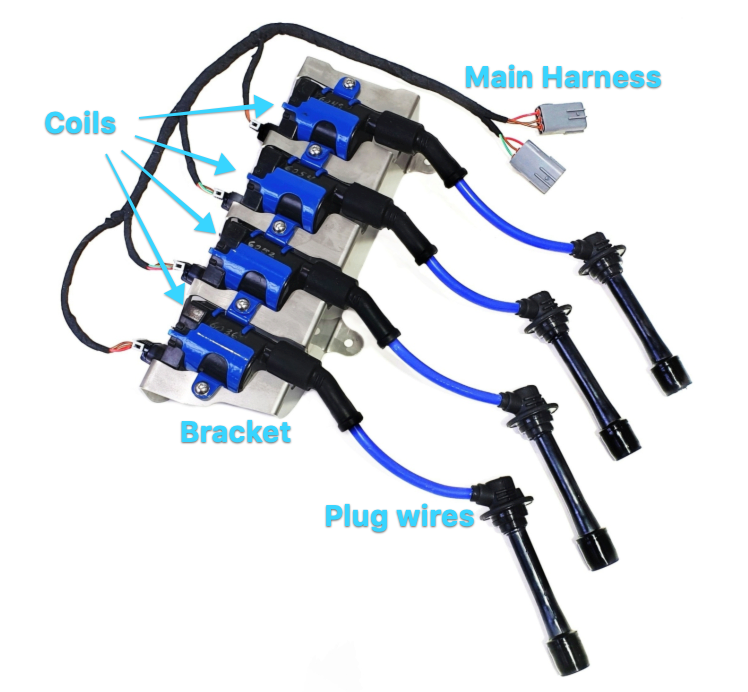
Let’s start with the mechanical installation of the bracket and coils. Remove the OEM coil packs (see the appropriate chassis year section for what to do with the connectors you remove). Install the LS2 coils onto the bracket with the supplied hardware - note that the latest version of the bracket comes with the coils pre-installed. De-torque all your valve cover bolts before removing the ones where the bracket goes. Connect the main harness to your coils. Mount the bracket to the intake side of your valve cover and then follow the torque specs and order in the service manual.
The spark plug wires are 3 different lengths. A shorter one, a middle one, and two longer ones. We designed them to be installed long, long, medium, short from front to back, however, you can install these however you want to be the most aesthetically pleasing. On 1990-2000 engines the plug wires should fit in without any fuss. Once the wire clicks onto the spark plug, you may need to press the top of the boot a bit to get it to seal nicely in place. 2001-2005 engines have slightly smaller plug boot holes, and also two of the spark plug holes are raised slightly. The plug wires should fit the lower holes with a slight gap. For the raised holes, a little trimming is required to slim down the boot.
For wiring, the instructions are different for 1990-93, 94-00, and 01+ chassis. Please follow the guide for your year of car. The instructions are the same regardless of which year engine you have. The following diagrams maybe be helpful for 1990-2000 chassis owners.
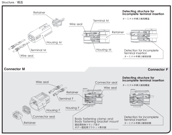
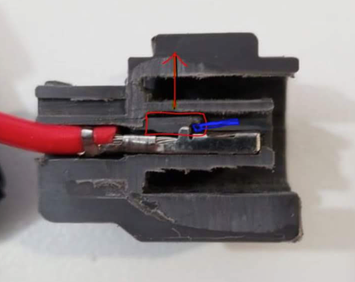
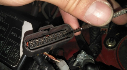
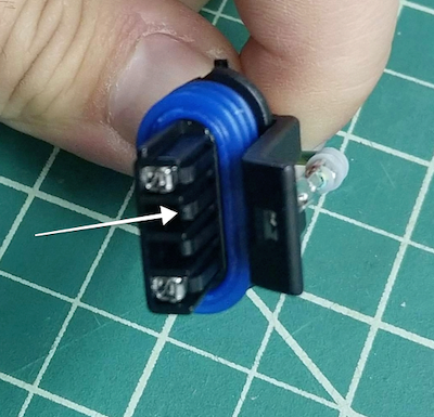
Cross section of connector. Insert small screwdriver where marked in blue. Lift the tab circled in red. The wire should then easily pull out the back of the connector.
1990-1993
For these early year cars, we are replacing the stock igniter, so it’s a little more involved. Most issues arise when pinning the wires from the igniter connector to the supplied 3-pin connectors.
Unplug and remove the igniter (located near the fuse box).
Connect the extension harness to the main LS coil harness and route accordingly so that the other end sits near the 8-way igniter connector. Note that there are two versions of the main harness. V1 has brown wires, and with that version simply match up the colors of the wires to the 90-93 patch. V2, which began shipping in September 2019, does not have any brown wires. With the V2 harness, match up the red wires and the green wires to the 90-93 patch to ensure they are plugged correctly.
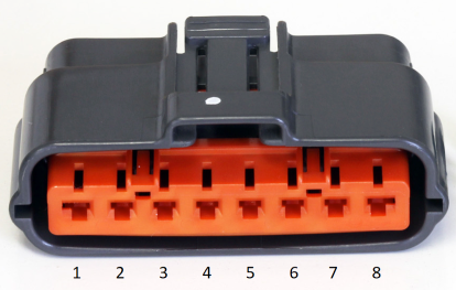
Carefully remove the orange secondary lock from the 8-way connector.
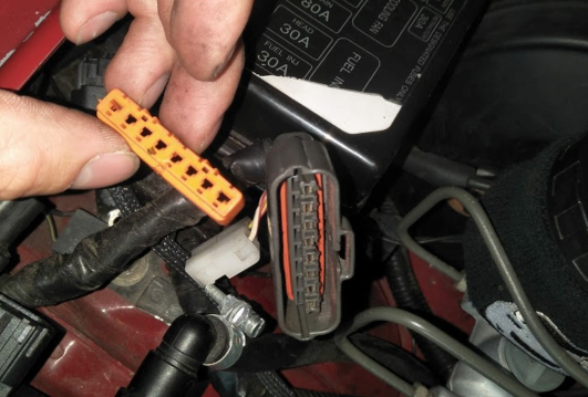
Using a very small jewelers flat head screwdriver or equivalent, lift the terminal retainer inside the connector and remove the number 2, 3, 6 and 7 terminals from the connector.
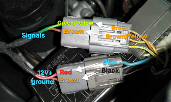
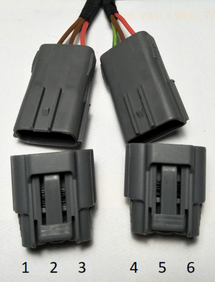
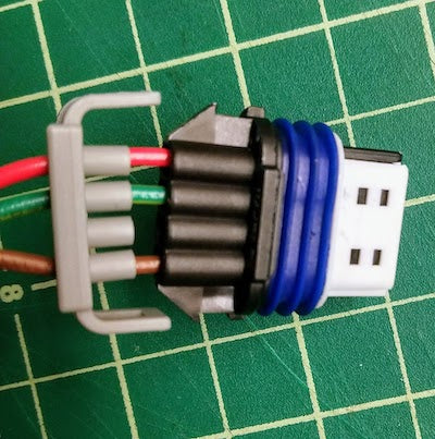
Insert the wires into the two provided 3-way connectors following the below tables to ensure the correct positions. There are two brown wires on the harness extension. We know this is confusing. Please look carefully at the image of the connectors to ensure the correct wire arrangement.
Note that in April 2020 we released the V2 NA6 patch with more intuitive wire colors. See the table below to identify the wiring of your version.
|
NA6 |
||
|
FF Patch V1.... |
FF Patch V2.... |
OEM Igniter Side |
|
Green/Yellow (signal).... |
Green |
7 – Brown |
|
Brown (signal) |
Blue |
2 – Brown/Yellow |
|
Red (12V+) |
Red |
3 – Blue |
|
Brown (ground) |
Black |
6 – Black |
Fit the orange secondary locks to the connectors.
Connect the two 3-way connectors into the matching connectors on the LS coil harness. Look carefully at the labeled picture above to make sure they are correctly connected. Optionally mark one set of matching connectors with a permanent marker to prevent future mix up.
ECU to Tachometer Connection Instructions:
-
Connecting the ECU to the Tachometer:
- Find the igniter connector; identify pins 4 and 5 (typically colored Yellow/Blue and Black/White).
- Join pins 4 and 5 to allow the ECU direct communication with the gauge cluster tachometer, enabling ECU control over the tachometer.
- Connect a suitable output from the ECU to pin 2I on the ECU connector for proper functionality.
-
Soldering for Reliable Connection:
- Securely solder together pins 4 and 5 on the ignitor for a stable connection.
-
Resistor Installation in Diagnostic Box:
- In the Diagnostic box, install a 1k ohm resistor between the B+ and IGN- terminals for the correct tachometer operation.
-
Tachometer Settings in MegaSquirt:
- In MegaSquirt settings, set the tachometer output to "TACH OUT".
- Ensure all tach settings are correctly adjusted for proper tachometer functionality.
1994-2000
The 4-pin connector used by this year-range is no-longer produced, however it only uses 3 pins anyway. In this install, you de-pin the 4-pin connectors and pin the wires into the same type of 3-pin connectors used by 2001+ cars. Alright then, let’s get to it!
Take your 4-pin coil pack connectors and using a very small jewelers flat head screwdriver or equivalent, lift the terminal retainer inside the connector and pull the wires out of the rear of the connector housing. If the connector has an orange secondary lock, it will have to be carefully removed before removing the terminals.
Insert the wires into the two provided 3-way connectors following the below tables and diagram to ensure the correct positions.
In September 2019 we released V2 of our harness, which has more intuitive wire colors. Please note which version you have from the table below when matching up to your vehicle harness.
|
FF Coil Harness Side |
94-97 OEM Harness Side |
99-00 OEM Harness Side |
|
Connector 1 |
||
|
Blue (Position 1 - signal) |
Brown/Yellow |
Brown/Yellow |
|
Black (Position 2 - ground) |
Black |
Black |
|
Red (Position 3 - 12V+) |
Blue |
Black/White |
|
Connector 2 |
||
|
Green (Position 4 - signal) |
Brown |
Brown |
|
Black (Position 5 - ground) |
Black |
Black |
|
Red (Position 6 - 12V+) |
Blue |
Black/White |
Early NA8 will have two spare black/white wires left over. Insulate them and tape them back to the harness.
Connect the two 3-way connectors into the matching connectors on the LS coil harness. Match the connectors according to the wire colours above. Mixing them up will result in cylinders firing in the wrong order. Optionally mark one set of matching connectors with a permanent marker to prevent future mix up.
2001-2005
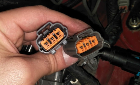
NB2 cars have the most straight forward installation. All you are doing is connecting the OEM plugs to the FlowForce harness. Connect the longer OEM 3-way connector to the matching LS coil connector with a green wire. Connect the second shorter OEM 3-way connector to the matching LS coil connector with two brown wires. Mixing these connectors up will result in cylinders firing in the wrong order.
All Years
With the wiring done and the bracket, coils, and plug wires installed, it’s time to set up your tune. The below is for Megasquirt 3, and other MS version and stand along ECUs should be similar.
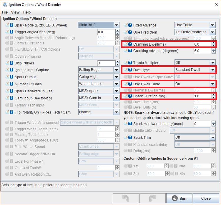
Start by setting up your coil settings
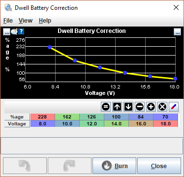
Then set up your dwell table and battery correction.
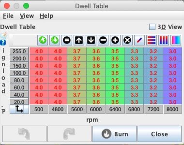
Note that MS2 doesn’t have Dwell tables. Just set nominal dwell to 3.0 and send it.
Now it’s time to drive your car! You will likely need to slightly tune much if not all of your fuel table. LS coils pack a meatier punch and will give you more complete combustion.
Sequential Add-On
The FlowForce LS coil harness comes wired for wasted spark for plug and play ease, and is also upgradeable for sequential ignition. The switch to sequential is fully reversible, and the upgrade kit is available on this site.
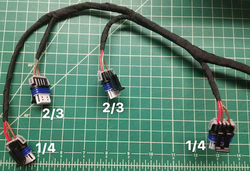
The middle connectors are for cylinders 2 and 3 and the outer connectors are for cylinders 1 and 4 in batch configuration. When switching to sequential, the signal wires that are in the harness already will fire cylinder 1 and 3, and you’ll repin one 1/4 connector to your ECU to fire cylinder 4 and one 2/3 connector to cylinder 2. You can choose which connectors you re-pin based on the layout of your harness in your car, but this would typically be that the coil connector farthest from the harness plug would be 1. On each connector you repin for sequential, you need to remove the middle wire and replace it with the new sequential wire. To make the upgrade fully reversible, insulate and tape back the old middle wire.
Start by removing the wire guard
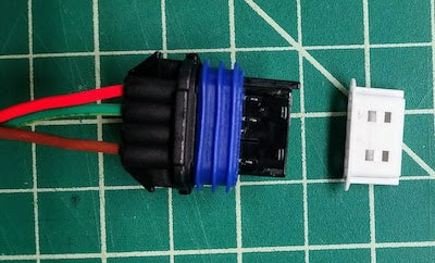
Then pull with firm careful pressure to remove the white cover
Once the wiring is complete at the harness, run the two new sequential wires back to your ecu, and splice to your spare ignition signal wires. Make the appropriate adjustments in your tuning software to run sequential.
If you have any questions, or have any feedback, please reach out to team@goflowforce.com